http://www.casa.ucl.ac.uk/richard/demos/planet/GameOfLifePlanet.html
The way this was created was as follows:
Step 1 – Create the Planet Mesh
I’ve defined my axes with x to the right, z up and y into the screen. This is slightly unusual, but maps to the ground plane which was originally XZ.
for z=0 to numZ-1
    for x=0 to numX-1
          ax=x/numX*2.0*PI-PI;
          az=z/numZ*PI-PI/2;
          cx=radius*cos(az)*sin(ax);
          cy=radius*cos(az)*cos(ax);
          cz=radius*sin(az);
          coords[x][z]=new Point3D(cx,cy,cz);
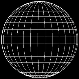
The mesh of points can be wrapped around in the x direction, but not Z, so we need an extra line of points at the South pole. I’ve also taken the radius to be 1.0 as using the unit sphere simplifies a lot of the graphics calculations that follow.
This gives you the following result:

Step 2 – Spin the World
Next I added an animation thread that increments ‘A’, the angle of rotation of the planet. In the rendering code for the mesh I rotate the points to spin the planet around the poles. The interesting thing here is that you don’t need the Y coordinate as there’s no projection, so that saves a few operations.
xp[i]=radius*(xpoints[i]*cos(A)+ypoints[i]*sin(A))
//yp[i]=radius*(xpoints[i]*sin(A)-ypoints[i]*cos(A))
zp[i]=radius*zpoints[i]
The back faces have been removed by using the direction between the surface normal and the viewer. Any face pointing away from the viewer is not drawn.
Step 3 – Add the Game of Life Simulation
I already had an implementaion of this in Java, so I just pulled it into the project. The following wikipedia article contains everything you could every need to know about Conway’s Game of Life:
http://en.wikipedia.org/wiki/Conway’s_Game_of_Life
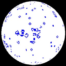
Then it’s just a case of running the ALife simulation and linking the output to the cells in the planet mesh. The grid used for the Game of Life simulation and the mesh making up the planet are the same size, so there is a simple one to one relationship.

Step 4 – Lights
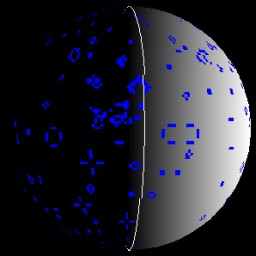
To improve the realism, I added some lighting using Lambert’s cosine rule. The direction of the light is [-1.0, 0.0, 0.0] which makes the intensity calculation straightforward. The light is assumed to be far enough away that the direction of the light is constant over the whole object. The planet is a unit sphere centred on the origin, so the normal to the surface patch is just a ray through the origin and the centre of the patch. I’ve actually taken the top left corner to save having to calculate the centre point, but it doesn’t make much difference to the effect.
According to Lambert’s cosine rule, the intensity of the patch is proportional to the cosine of the angle between the surface normal and the light. We use the dot product of the two vectors to get the cosine of the acute angle between them. As both vectors are already normalised beforehand, we don’t have to normalise them ourselves.
In this view, any game of life cell that is ‘on’ is drawn in blue, while any that are ‘off’ are white. The white colour uses the diffuse lighting while the blue is drawn as emissive so you can see the patterns as they go around the dark side of the globe. I’ve also added a line at the 0 and 180 degree longitude positions so you can see the planet rotating.
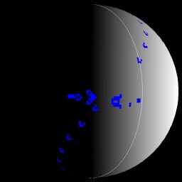
Here is an image of a “Gosper Glider Gun” about to shoot gliders at itself from around the other side of the planet. The applet link below contains a number of the more common patterns.

- Gosper Glider Gun
http://www.casa.ucl.ac.uk/richard/demos/planet/GameOfLifePlanet.html
