FBX Exporters Part 4

In the previous three parts, I outlined the plan for getting geometry from MapTube via C Sharp into an FBX file using the C++ SDK provided by Autodesk. This final part shows data in a world map exported from MapTube and imported into 3DS Max.

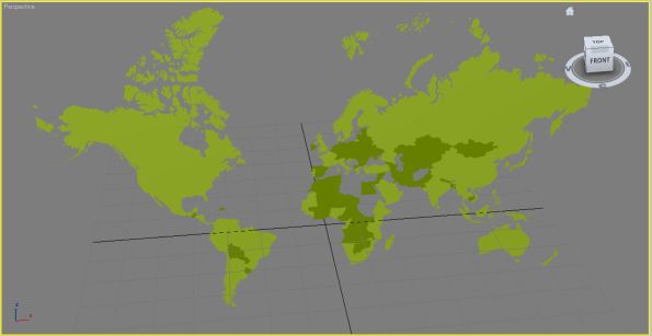
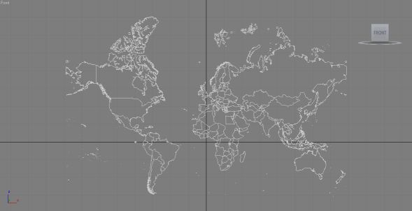
The above image shows the world countries 2010 outline from MapTube. There a few countries missing as there was no data for them in the original dataset, so they show as blank on a MapTube map and their geometry is not exported. This is more visible in the perspective view where you can see the holes in Africa and the Middle East:

The exported geometry will eventually be coloured in the same way as MapTube, but for the moment all the geometry objects have a green material assigned to them.

The final export file can be downloaded from the following link: MyFBXExport


It’s worth pointing out that I’ve had a number of problems with the Quicktime FBX plugin that comes with the Autodesk FBX SDK. It seems to crash every time I close it and when displaying the above file there are some significant problems with how it renders the geometry. Most notably around the Hudson Bay area in Canada, parts of Europe and much of Russia. As it displays fine in Max, I can only assume this is a limitation of the Quicktime FBX renderer. I’ve also had to do some re-scaling of the geometry as it is exported in the Google Mercator projection, using metres. This means that the numbers are too big for Max to handle, so I’ve had to rescale them.

To recap on how this process works, here are the development steps needed to achieve it:

1. A C Sharp program which is a modification of the MapTubeD tile rendering procedure reads the geometry and data from the MapTube server and returns it as an iteration of SqlGeometry objects.

2. Each SqlGeometry object is simplified using the Reduce operation as we don’t need the full level of detail in the output FBX file.

3. The C Sharp program uses native methods in a C++ DLL, which I’ve written to control the operation of the FBX exporter in Autodesk’s SDK. A handle to the FBX document and scene that we want to create is obtained and then a native “AddGeometry” function is used on every geometry object until a final “WriteFile” function is called. The geometry is passed using the OGC well known binary format which is an efficient way of passing large blocks of complex geometry and is also independent of byte ordering.

The DLL which does the actual export is a 32 bit program with functions exported using C names rather than decorated C++ names to make it easy to link to the C Sharp function stubs. Internally, I’m using the GEOS library to parse the well known binary geometry, extract polygons and write the points to the FBX scene hierarchy.

That’s the proof of concept to demonstrate that this method works. The aim now is to see what we can do with geographic data now that we have the ability to load it into art tools like Max and Maya, game engines like Unity, or frameworks like XNA.


FBX Exporters Part 3

The first two parts of the FBX export process dealt with getting the FBX SDK working and exporting some simple geometry. Now what’s required is the ability to pass complex geometry from the MapTube side using C# over to the FBX side using C++. The obvious way to do this is to pass the geometry in the OGC well known binary format (WKB), so I’ve been looking at GEOS which is a C++ port of the Java Topology Suite (JTS). I’ve managed to use this in conjunction with the FBX exporter to create simple geometry from WKT which I’ve loaded into 3DS Max.

One of the problems I had was building a debug version of GEOS version 3.3.1 as the instructions aren’t quite right. The make command for a debug build is:

nmake /f makefile.vc BUILD_DEBUG=YES

As I’m using Visual Studio 2008, I had to run “autogen.bat” first to create the required header files, and also make sure I do a clean between the release build and the debug build. Once this library was built successfully, I could use the WKT reader to read in some test geometry and build an FBX exporter around it.

[c language=”++”]
string version = geos::geom::geosversion();
cout<<version;
//geom::Geometry* geos::io::WKBReader::read ( std::istream & is );
std::string poly("POLYGON ((30 10 0, 10 20 10, 20 40 20, 40 40 30, 30 10 0))");
cout<<poly<<endl;
WKTReader* reader = new WKTReader();
Geometry* geom = reader->read(poly);
delete reader;
[/c]

The entire FBX exporter is too big to replicate here, but the part that extracts the geometry from the GEOS geometry object and creates the FBX control points is as follows:

[c language=”++”]
//create control points
int NumPoints = geom->getNumPoints();
lMesh->InitControlPoints(NumPoints);
KFbxVector4* lControlPoints = lMesh->GetControlPoints();
CoordinateSequence* coords = geom->getCoordinates();
for (int i=0; i<NumPoints; i++)
{
lControlPoints[i]=KFbxVector4(coords->getOrdinate(i,0), coords->getOrdinate(i,1), coords->getOrdinate(i,2) );
cout<<coords->getOrdinate(i,0)<<","<<coords->getOrdinate(i,1)<<","<<coords->getOrdinate(i,2)<<endl;
}
[/c]

The only other thing I’ve done is to create a material for the polygon so it shows up as red in 3DS Max.

Now I’ve demonstrated that all the component parts work, the final stage of getting geometry from MapTube into 3DS Max will be to write a C++ library on top of the FBX exporter and GEOS which can be used as a native library from C#.

FBX Exporters Part 2

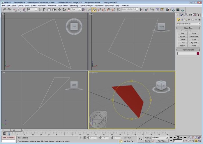
In the first FBX exporter post I got to the point where the export of simple geometry from one of the Autodesk SDK examples could be loaded by the Quicktime plugin. This used the SDK as a multithreaded statically linked library which I used with one of the examples to create a plane object. The following image shows a more complicated file containing a marker (red), custom geometry in the form of a cube (grey) and a camera (looks like a camera).
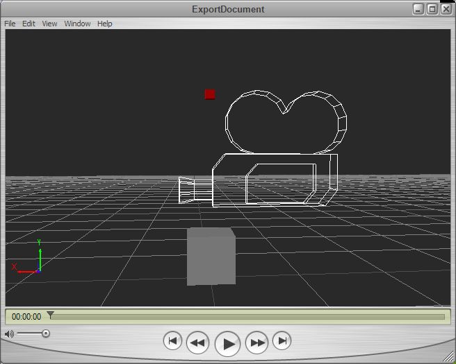
The code to get to this point is rather complicated, but I copied the UI Examples CubeCreator example program supplied with the SDK which showed how to set up the cube mesh with all the correct normals and textures.

The scene graph is set up with a camera, marker and mesh as follows:

[c language=”++”]
// build a minimum scene graph
KFbxNode* lRootNode = pScene->GetRootNode();
lRootNode->AddChild(lMarker);
lRootNode->AddChild(lCamera);
// Add the mesh node to the root node in the scene.
lRootNode->AddChild(lMeshNode);
[/c]

The creation of the mesh object prior to this is a lot more complicated:

[c language=”++”]
// Define the eight corners of the cube.
// The cube spans from
// -5 to 5 along the X axis
// 0 to 10 along the Y axis
// -5 to 5 along the Z axis
KFbxVector4 lControlPoint0(-5, 0, 5);
KFbxVector4 lControlPoint1(5, 0, 5);
KFbxVector4 lControlPoint2(5, 10, 5);
KFbxVector4 lControlPoint3(-5, 10, 5);
KFbxVector4 lControlPoint4(-5, 0, -5);
KFbxVector4 lControlPoint5(5, 0, -5);
KFbxVector4 lControlPoint6(5, 10, -5);
KFbxVector4 lControlPoint7(-5, 10, -5);

KFbxVector4 lNormalXPos(1, 0, 0);
KFbxVector4 lNormalXNeg(-1, 0, 0);
KFbxVector4 lNormalYPos(0, 1, 0);
KFbxVector4 lNormalYNeg(0, -1, 0);
KFbxVector4 lNormalZPos(0, 0, 1);
KFbxVector4 lNormalZNeg(0, 0, -1);

// Initialize the control point array of the mesh.
lMesh->InitControlPoints(24);
KFbxVector4* lControlPoints = lMesh->GetControlPoints();
// Define each face of the cube.
// Face 1
lControlPoints[0] = lControlPoint0;
lControlPoints[1] = lControlPoint1;
lControlPoints[2] = lControlPoint2;
lControlPoints[3] = lControlPoint3;
// Face 2
lControlPoints[4] = lControlPoint1;
lControlPoints[5] = lControlPoint5;
lControlPoints[6] = lControlPoint6;
lControlPoints[7] = lControlPoint2;
// Face 3
lControlPoints[8] = lControlPoint5;
lControlPoints[9] = lControlPoint4;
lControlPoints[10] = lControlPoint7;
lControlPoints[11] = lControlPoint6;
// Face 4
lControlPoints[12] = lControlPoint4;
lControlPoints[13] = lControlPoint0;
lControlPoints[14] = lControlPoint3;
lControlPoints[15] = lControlPoint7;
// Face 5
lControlPoints[16] = lControlPoint3;
lControlPoints[17] = lControlPoint2;
lControlPoints[18] = lControlPoint6;
lControlPoints[19] = lControlPoint7;
// Face 6
lControlPoints[20] = lControlPoint1;
lControlPoints[21] = lControlPoint0;
lControlPoints[22] = lControlPoint4;
lControlPoints[23] = lControlPoint5;

// We want to have one normal for each vertex (or control point),
// so we set the mapping mode to eBY_CONTROL_POINT.
KFbxGeometryElementNormal* lGeometryElementNormal= lMesh->CreateElementNormal();

lGeometryElementNormal->SetMappingMode(KFbxGeometryElement::eBY_CONTROL_POINT);

// Set the normal values for every control point.
lGeometryElementNormal->SetReferenceMode(KFbxGeometryElement::eDIRECT);

lGeometryElementNormal->GetDirectArray().Add(lNormalZPos);
lGeometryElementNormal->GetDirectArray().Add(lNormalXPos);
lGeometryElementNormal->GetDirectArray().Add(lNormalZNeg);
lGeometryElementNormal->GetDirectArray().Add(lNormalXNeg);
lGeometryElementNormal->GetDirectArray().Add(lNormalYPos);
lGeometryElementNormal->GetDirectArray().Add(lNormalYNeg);

// Array of polygon vertices.
int lPolygonVertices[] = { 0, 1, 2, 3, 4, 5, 6, 7, 8, 9, 10, 11,12, 13,
14, 15, 16, 17, 18, 19, 20, 21, 22, 23 };

// Create UV for Diffuse channel.
KFbxGeometryElementUV* lUVDiffuseElement = lMesh->CreateElementUV( "DiffuseUV");
K_ASSERT( lUVDiffuseElement != NULL);
lUVDiffuseElement->SetMappingMode(KFbxGeometryElement::eBY_POLYGON_VERTEX);
lUVDiffuseElement->SetReferenceMode(KFbxGeometryElement::eINDEX_TO_DIRECT);

KFbxVector2 lVectors0(0, 0);
KFbxVector2 lVectors1(1, 0);
KFbxVector2 lVectors2(1, 1);
KFbxVector2 lVectors3(0, 1);

lUVDiffuseElement->GetDirectArray().Add(lVectors0);
lUVDiffuseElement->GetDirectArray().Add(lVectors1);
lUVDiffuseElement->GetDirectArray().Add(lVectors2);
lUVDiffuseElement->GetDirectArray().Add(lVectors3);

//Now we have set the UVs as eINDEX_TO_DIRECT reference and in eBY_POLYGON_VERTEX mapping mode
//we must update the size of the index array.
lUVDiffuseElement->GetIndexArray().SetCount(24);

// Create polygons. Assign texture and texture UV indices.
for(int i = 0; i < 6; i++)
{
// all faces of the cube have the same texture
lMesh->BeginPolygon(-1, -1, -1, false);

for(int j = 0; j < 4; j++)
{
// Control point index
lMesh->AddPolygon(lPolygonVertices[i*4 + j]);

// update the index array of the UVs that map the texture to the face
lUVDiffuseElement->GetIndexArray().SetAt(i*4+j, j);
}

lMesh->EndPolygon();
}

[/c]

So, we have to define the vertices (control points in the language of the SDK), normals and UV coordinates for the mesh to show in the Quicktime viewer. It’s also worth mentioning that I’ve had to force the output FBX file from the exporter to be in binary format as the viewer refuses to load the ASCII format FBX. In addition to this, I’m still getting application crashes when I close the Quicktime viewer.

Now I have the ability to create custom geometry, the next step is to write an interface to allow me to pass geographic data to the exporter via C#. After giving this some thought, the obvious solution is to pass well-known binary (WKB) from the C# program to the C++ library as a block of bytes. This is a relatively easy format to produce and decode into geometry, so shouldn’t take long to write.

Part three will deal with the mechanics of getting actual geometry to the exporter and generating an FBX file from real geographic data.

Exporting Geographic Data in FBX Files

I’ve been looking at how to export the geographic information contained in a MapTube map into an art tool like 3DS Max or Maya. The reason for this is firstly to make it easier to produce high quality geographic presentations, but also, by employing a recognised art tool chain, we can also get the data into 3D visualisation systems built around XNA (XBox) or Unity.

Originally, I was going to implement a 3DS exporter as this is a well-used format that would allow geometry to be imported by Google Sketchup, Blender, or a long list of professional art tools. After coming across Autodesk’s FBX SDK, I decided to create an FBX exporter instead. Although this is a format that can’t be loaded by either Sketchup or Blender, the SDK is quite flexible and can also export Collada (DAE) and Wavefront OBJ files which the free tools can import. In addition to this, it can be imported by both Unity and XNA.

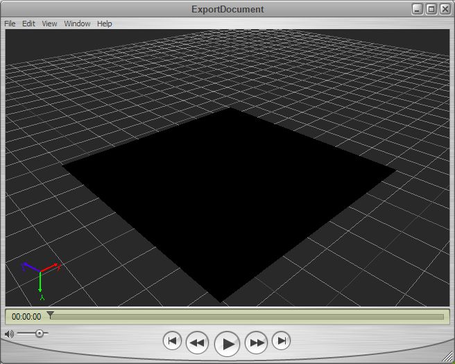
Autodesk supply a viewer plugin for Quicktime, but I had some problems getting this to work with my first export attempts. The example below shows a simple screenshot:

Although a flat black plane on a grey background isn’t fantastic for a first attempt, it took a while to get this far as the examples don’t tell you that the Quicktime viewer doesn’t like ASCII format FBX files and you have to change the example format to BINARY.

[c language=”++”]
//altered export from ASCII to Binary
int lFormatIndex, lFormatCount = pSdkManager->GetIOPluginRegistry()->GetWriterFormatCount();

for (lFormatIndex=0; lFormatIndex<lFormatCount; lFormatIndex++)
{
if (pSdkManager->GetIOPluginRegistry()->WriterIsFBX(lFormatIndex))
{
KString lDesc =pSdkManager->GetIOPluginRegistry()->GetWriterFormatDescription(lFormatIndex);
printf("%s\n",lDesc.Buffer()); //print out format strings
//char *lASCII = "ascii";
char *lBinary = "binary";
if (lDesc.Find(/*lASCII*/lBinary)>=0)
{
pFileFormat = lFormatIndex;
break;
}
}
}
[/c]

This is a copy of the “ExportDocument” example that comes with the SDK, but with the type changed to binary to allow it to load.

The next problem is learning how to create my own geometry and figuring out a way of connecting the native C++ library to the managed C# code used by MapTube. My initial thought was to create a managed wrapper for the FBX SDK and use marshalling, but, on further examination of the SDK, it’s much too complicated to do in any reasonable amount of time. So, plan B is to write the code to do the export as a native C++ process, expose enough methods to allow this to be controlled through marshalling and interop via the C# code and do the FBX export through that route. This only depends on being able to marshall the large amount of geometry data, but this should be possible to work out.

After these first experiments, it’s looking like the pattern will be something like a reader/writer object with a choice of export formats as FBX, Collada or OBJ to allow the assets to be loaded into as many art packages as possible.

The next post will cover the generation of the geometry and its export to FBX.

Importing GPS Tracks into 3DS Max

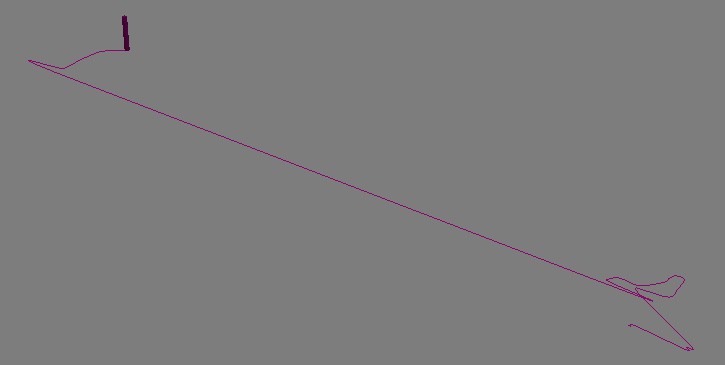
A GPS track imported into 3DS Max from a GPX File

While playing around with 3DS Max 2009 for some of our GENeSIS work, I happened to notice that it’s now possible to use .net assemblies in MaxScript. My first thought was to use this for some of our agent based modelling work, but when Fabian Neuhaus asked about importing GPX files, I saw a really easy way of doing this.

The “System.Xml” assembly in .net makes parsing the GPX file extremely simple. A GPX file is nothing more than an xml file containing a list of trackpoints with a lat/lon and a time. The following script parses a GPX file and generates an animation of a box following a spline which follows the GPS track:

Maxscript GPX Importer

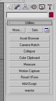
In order to use this, you have to run the script from the MaxScript rollout on the Utilities menu (click the hammer on the right hand side). Then click the “MaxScript” and “Run Script”. Point the file dialog to the file dowloaded from above and it should run.

The script creates a rollout window which allows you to browse for a GPX file to upload. After this is done, the file will be imported, resulting in an “Import Successful” message.

The only problems you might get are to do with the format of time recorded by the GPS in the track. If the import refuses to work, then you might need to change the time format as indicated by the comments in the MaxScript file.

One other thing worth mentioning is that the lat and long coordinates have been multiplied by 1000 in order to cope with a lack of granularity in Max. After producing this version of the script which loads data in the WGS84 coordinate system, I then created another version which reprojects the data into the OSGB36 system that Ordnance Survey uses in the UK. This means that we can match up the GPS tracks in Max with our own data on building footprints which comes from Ordnance Survey.

For movies showing the animated GPX tracks, have a look at the Urban Tick website:

http://urbantick.blogspot.com/2009/09/gps-tracks-running-in-3ds-max.html

http://urbantick.blogspot.com/