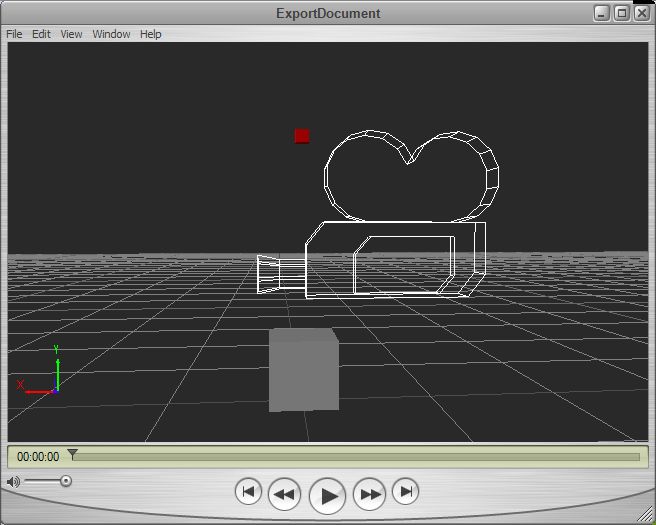
In the first FBX exporter post I got to the point where the export of simple geometry from one of the Autodesk SDK examples could be loaded by the Quicktime plugin. This used the SDK as a multithreaded statically linked library which I used with one of the examples to create a plane object. The following image shows a more complicated file containing a marker (red), custom geometry in the form of a cube (grey) and a camera (looks like a camera).
The code to get to this point is rather complicated, but I copied the UI Examples CubeCreator example program supplied with the SDK which showed how to set up the cube mesh with all the correct normals and textures.
The scene graph is set up with a camera, marker and mesh as follows:
[c language=”++”]
// build a minimum scene graph
KFbxNode* lRootNode = pScene->GetRootNode();
lRootNode->AddChild(lMarker);
lRootNode->AddChild(lCamera);
// Add the mesh node to the root node in the scene.
lRootNode->AddChild(lMeshNode);
[/c]
The creation of the mesh object prior to this is a lot more complicated:
[c language=”++”]
// Define the eight corners of the cube.
// The cube spans from
// -5 to 5 along the X axis
// 0 to 10 along the Y axis
// -5 to 5 along the Z axis
KFbxVector4 lControlPoint0(-5, 0, 5);
KFbxVector4 lControlPoint1(5, 0, 5);
KFbxVector4 lControlPoint2(5, 10, 5);
KFbxVector4 lControlPoint3(-5, 10, 5);
KFbxVector4 lControlPoint4(-5, 0, -5);
KFbxVector4 lControlPoint5(5, 0, -5);
KFbxVector4 lControlPoint6(5, 10, -5);
KFbxVector4 lControlPoint7(-5, 10, -5);
KFbxVector4 lNormalXPos(1, 0, 0);
KFbxVector4 lNormalXNeg(-1, 0, 0);
KFbxVector4 lNormalYPos(0, 1, 0);
KFbxVector4 lNormalYNeg(0, -1, 0);
KFbxVector4 lNormalZPos(0, 0, 1);
KFbxVector4 lNormalZNeg(0, 0, -1);
// Initialize the control point array of the mesh.
lMesh->InitControlPoints(24);
KFbxVector4* lControlPoints = lMesh->GetControlPoints();
// Define each face of the cube.
// Face 1
lControlPoints[0] = lControlPoint0;
lControlPoints[1] = lControlPoint1;
lControlPoints[2] = lControlPoint2;
lControlPoints[3] = lControlPoint3;
// Face 2
lControlPoints[4] = lControlPoint1;
lControlPoints[5] = lControlPoint5;
lControlPoints[6] = lControlPoint6;
lControlPoints[7] = lControlPoint2;
// Face 3
lControlPoints[8] = lControlPoint5;
lControlPoints[9] = lControlPoint4;
lControlPoints[10] = lControlPoint7;
lControlPoints[11] = lControlPoint6;
// Face 4
lControlPoints[12] = lControlPoint4;
lControlPoints[13] = lControlPoint0;
lControlPoints[14] = lControlPoint3;
lControlPoints[15] = lControlPoint7;
// Face 5
lControlPoints[16] = lControlPoint3;
lControlPoints[17] = lControlPoint2;
lControlPoints[18] = lControlPoint6;
lControlPoints[19] = lControlPoint7;
// Face 6
lControlPoints[20] = lControlPoint1;
lControlPoints[21] = lControlPoint0;
lControlPoints[22] = lControlPoint4;
lControlPoints[23] = lControlPoint5;
// We want to have one normal for each vertex (or control point),
// so we set the mapping mode to eBY_CONTROL_POINT.
KFbxGeometryElementNormal* lGeometryElementNormal= lMesh->CreateElementNormal();
lGeometryElementNormal->SetMappingMode(KFbxGeometryElement::eBY_CONTROL_POINT);
// Set the normal values for every control point.
lGeometryElementNormal->SetReferenceMode(KFbxGeometryElement::eDIRECT);
lGeometryElementNormal->GetDirectArray().Add(lNormalZPos);
lGeometryElementNormal->GetDirectArray().Add(lNormalZPos);
lGeometryElementNormal->GetDirectArray().Add(lNormalZPos);
lGeometryElementNormal->GetDirectArray().Add(lNormalZPos);
lGeometryElementNormal->GetDirectArray().Add(lNormalXPos);
lGeometryElementNormal->GetDirectArray().Add(lNormalXPos);
lGeometryElementNormal->GetDirectArray().Add(lNormalXPos);
lGeometryElementNormal->GetDirectArray().Add(lNormalXPos);
lGeometryElementNormal->GetDirectArray().Add(lNormalZNeg);
lGeometryElementNormal->GetDirectArray().Add(lNormalZNeg);
lGeometryElementNormal->GetDirectArray().Add(lNormalZNeg);
lGeometryElementNormal->GetDirectArray().Add(lNormalZNeg);
lGeometryElementNormal->GetDirectArray().Add(lNormalXNeg);
lGeometryElementNormal->GetDirectArray().Add(lNormalXNeg);
lGeometryElementNormal->GetDirectArray().Add(lNormalXNeg);
lGeometryElementNormal->GetDirectArray().Add(lNormalXNeg);
lGeometryElementNormal->GetDirectArray().Add(lNormalYPos);
lGeometryElementNormal->GetDirectArray().Add(lNormalYPos);
lGeometryElementNormal->GetDirectArray().Add(lNormalYPos);
lGeometryElementNormal->GetDirectArray().Add(lNormalYPos);
lGeometryElementNormal->GetDirectArray().Add(lNormalYNeg);
lGeometryElementNormal->GetDirectArray().Add(lNormalYNeg);
lGeometryElementNormal->GetDirectArray().Add(lNormalYNeg);
lGeometryElementNormal->GetDirectArray().Add(lNormalYNeg);
// Array of polygon vertices.
int lPolygonVertices[] = { 0, 1, 2, 3, 4, 5, 6, 7, 8, 9, 10, 11,12, 13,
14, 15, 16, 17, 18, 19, 20, 21, 22, 23 };
// Create UV for Diffuse channel.
KFbxGeometryElementUV* lUVDiffuseElement = lMesh->CreateElementUV( "DiffuseUV");
K_ASSERT( lUVDiffuseElement != NULL);
lUVDiffuseElement->SetMappingMode(KFbxGeometryElement::eBY_POLYGON_VERTEX);
lUVDiffuseElement->SetReferenceMode(KFbxGeometryElement::eINDEX_TO_DIRECT);
KFbxVector2 lVectors0(0, 0);
KFbxVector2 lVectors1(1, 0);
KFbxVector2 lVectors2(1, 1);
KFbxVector2 lVectors3(0, 1);
lUVDiffuseElement->GetDirectArray().Add(lVectors0);
lUVDiffuseElement->GetDirectArray().Add(lVectors1);
lUVDiffuseElement->GetDirectArray().Add(lVectors2);
lUVDiffuseElement->GetDirectArray().Add(lVectors3);
//Now we have set the UVs as eINDEX_TO_DIRECT reference and in eBY_POLYGON_VERTEX mapping mode
//we must update the size of the index array.
lUVDiffuseElement->GetIndexArray().SetCount(24);
// Create polygons. Assign texture and texture UV indices.
for(int i = 0; i < 6; i++)
{
// all faces of the cube have the same texture
lMesh->BeginPolygon(-1, -1, -1, false);
for(int j = 0; j < 4; j++)
{
// Control point index
lMesh->AddPolygon(lPolygonVertices[i*4 + j]);
// update the index array of the UVs that map the texture to the face
lUVDiffuseElement->GetIndexArray().SetAt(i*4+j, j);
}
lMesh->EndPolygon();
}
[/c]
So, we have to define the vertices (control points in the language of the SDK), normals and UV coordinates for the mesh to show in the Quicktime viewer. It’s also worth mentioning that I’ve had to force the output FBX file from the exporter to be in binary format as the viewer refuses to load the ASCII format FBX. In addition to this, I’m still getting application crashes when I close the Quicktime viewer.
Now I have the ability to create custom geometry, the next step is to write an interface to allow me to pass geographic data to the exporter via C#. After giving this some thought, the obvious solution is to pass well-known binary (WKB) from the C# program to the C++ library as a block of bytes. This is a relatively easy format to produce and decode into geometry, so shouldn’t take long to write.
Part three will deal with the mechanics of getting actual geometry to the exporter and generating an FBX file from real geographic data.

